Versapak Smart Charger Mark II
A couple of years ago I wrote an article for Nuts and
Volts magazine (which they published in Servo, a sister publication) on
rebuilding the dumb little chargers for Versapak batteries into "smart"
chargers. I then sold circuit boards and kits to people
who were interested building them. They sold pretty slow, in fact I
still have a bunch of the boards.
Then a couple of things happened:
1) the manufacture of the chip I used in the design stopped making
those chips
2) I kept getting people asking for a finished board, not a kit.
Under pressure from customers, I assembled a "drop in" board that I
also sold. However, as the design used SMT parts on both sides of the
board, it was a pain to assemble, so I had to ask a pretty penny for it.
I toyed with the idea for a couple of years of re-doing the design so
it would be a little easier to manufacture. Mainly changing the
chip to a newer (and currently in production) one, and putting all the
parts on the same side so I could reflow the boards.
About six months ago I decided that the effort really wasn't worth it,
that the number sales didn't support the amount of work that would have
to go into the redesign, so I stopped selling the pre-assembled boards.
Since, then, of course I have gotten like 10 people ask about them...
I finally relented and redesigned the board to use a more modern chip,
and put (most) of the parts on the same side.
Advantages of the new board:
-uses a more sophisticated chip (better be, costs
like 3X as much as the old one)
-integrated thermal monitoring on the new design
-new design uses switch mode instead of linear mode
to control the charging. what this means, basically, is that it is much
more efficient, and puts out very little heat
disadvantage:
-the parts are more expensive.
By expanding the board into all easily available space in the VP130 charger I was able to get both switch mode charging circuits on the same side of the board. There are still a few SMT parts
on the top, but enough of them are on the bottom to be able to use the pick and place machine to assemble them, and to reflow them instead of soldering them by hand. This means the manual labor of doing the boards is low enough that I can offer the "drop in" kit at a reasonable price.
I thought of providing the battery connector clips with these kits, but bending them up is non-trivial. Also, the VP130 chargers are ubiquitous, and you need one of them for the case anyway.
Provided:
basic kit:
-drop in switch mode Versapak smart/fast charger board
complete kit
-drop in switch mode Versapak smart/fast charger board
-power pigtail
-solder wick (to remove battery connectors)
-small bit of solder
-12V 2A power supply (US plug configuration)
tools needed:
-soldering iron (40W or better preferred)
-#2 Phillips screwdriver
other needed:
-sacrificial VP130 charger
-power supply (if you didn't get it from me)
-technically you will need a 1
amp supply, voltage anywhere from 9V to 24V DC. I recommend a 12V 2A
supply.
Following are installation instructions:
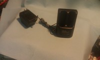
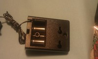
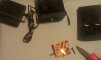
Left is a picture of the sacrificial charger, you will need to use the VP130 dual charger, that is what the board is designed to fit into. Second picture is a shot of the back with the two screws that you will need to remove in order to pull the case apart.
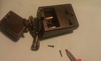
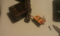
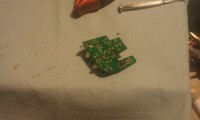
pull existing board out and set it aside. clip the wires and remove the original power supply. Either dispose of it properly or stick it in your supply of spare power supplies. Keep the old board for now, you are going to need to pull the clips off to re-use them on the new board.
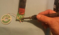
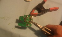
Hold the board in some kind of clamp or vice to make things easier. Use solder wick to remove as much of the solder holding the clips on as you can. While heating with the soldering iron, bend the little tabs up with a small screwdriver.
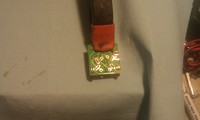
while heating connectors, gently remove them. solder the connectors into the new board. make sure they are oriented correctly, and that they are seated all the way.
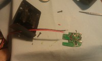
fish the
pigtail through the hole in the back of the VP130 case and
solder it to the board.
-or you can solder the power supply wires directly
to the board. your choice. if you hook it up backwards it will just not work, it is
polarity protected.
-note that for this batch of boards you may need to trim a couple of the strands
off the supplied pigtail, the holes in the board are just slightly to small. I will fix in next revision.
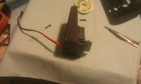
install board:
-make sure it is fully seated
Install original cover and replace screws.
plug in power supply,
charge batteries.
NOTE: about top off charging. In some cases older batteries won't be fully charged when done fast charging. This is a limitation of the technology, and there is nothing I can do about it.
This charger board will go into "top off" mode when done fast charging, and will finish topping off your batteries in about five and half hours (325 minutes), then go into maintenance mode.
status lights:
battery absent:
no light
fast charge pending:
fast blink red
(note, if you put a fully dead battery in it will go into trickle mode till the battery has enough voltage to accept charge, and will blink fast red while it is waiting)
fast charging:
red
fast charge complete, top-off, and/or trickle mode engaged:
green
.
